This is the Revision C verion of the AnalogIn4 RoboBrick. The status of this project is work in progress.
This document is also available in PDF format.
The AnalogIn4 RoboBrick allows for the input of up to 4 analog voltages between 0 and 5 volts with a resolution of 8 bits.
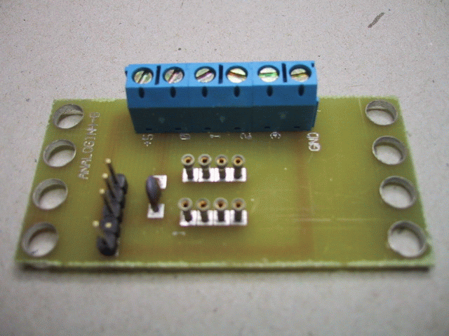
A picture of the AnalogIn4-B RoboBrick is shown below:
The AnalogIn4 RoboBrick is continuously reading the analog inputs from its four A/D pins. The controlling program can just read the results of the digital conversion, or it can have the result down converted into a single binary bit. Each pin has has a threshold high and threshold low register that is used for the down conversion. Whenever the digital conversion exceeds the high threshold register, the down coversion results in a 1. Whenever the digital conversion is lower than the low threshold register, the down conversion results in a 0. A hysterisis effect can be introduced by having some spread between the high and low threshold values.
There AnalogIn4 RoboBrick operates in either regular mode or Vref mode. In regular mode, all four inputs are A/D converted between 0 and 5 volts. In Vref mode, input 1 is used as Vref, the highest expected input voltage, and there remaining three inputs are A/D converts betweeen 0 and Vref.
After the down coversions to binary bits, the result is 4-bits of binary data. A complement mask can be used to selectively invert individual bits in the 4-bit data.
The AnalogIn4 RoboBrick supports RoboBrick Interrupt Protocol for those lines that are being used as inputs. The interrupt pending bit is set whenever the the formula:
L&(~I) | H&I | R&(~P)&I | F&P&(~I)is non-zero, where:
In addition to the common shared commands and the shared interrupt commands, the AnalogIn4 RoboBrick supports following commands:
| Command | Send/ Receive |
Byte Value | Discussion | |||||||
|---|---|---|---|---|---|---|---|---|---|---|
| 7 | 6 | 5 | 4 | 3 | 2 | 1 | 0 | |||
| Read Pin | Send | 0 | 0 | 0 | 0 | 0 | 0 | b | b | Read pin bb and respond with 8-bit value vvvvvvvv |
| Send | v | v | v | v | v | v | v | v | ||
| Read Binary Values | Send | 0 | 0 | 0 | 0 | 0 | 1 | 0 | 0 | Return the binary values abcd (after XOR'ing with complement mask) |
| Receive | 0 | 0 | 0 | 0 | a | b | c | d | ||
| Read Raw Binary | Send | 0 | 0 | 0 | 0 | 0 | 1 | 0 | 1 | Return the raw binary values abcd (no XOR with complement mask) |
| Receive | 0 | 0 | 0 | 0 | a | b | c | d | ||
| Reset | Send | 0 | 0 | 0 | 0 | 0 | 1 | 1 | 0 | Reset everything to zero |
| Read Complement Mask | Send | 0 | 0 | 0 | 0 | 1 | 0 | 0 | 0 | Return and return the complement mask cccc |
| Receive | 0 | 0 | 0 | 0 | c | c | c | c | ||
| Read High Mask | Send | 0 | 0 | 0 | 0 | 1 | 0 | 0 | 1 | Return and return the high mask hhhh |
| Receive | 0 | 0 | 0 | 0 | h | h | h | h | ||
| Read Low Mask | Send | 0 | 0 | 0 | 0 | 1 | 0 | 1 | 0 | Return and return the high mask llll |
| Receive | 0 | 0 | 0 | 0 | l | l | l | l | ||
| Read Raising Mask | Send | 0 | 0 | 0 | 0 | 1 | 0 | 1 | 1 | Return and return the raising mask rrrr |
| Receive | 0 | 0 | 0 | 0 | r | r | r | r | ||
| Read Falling Mask | Send | 0 | 0 | 0 | 0 | 1 | 1 | 0 | 0 | Return and return the falling mask ffff |
| Receive | 0 | 0 | 0 | 0 | f | f | f | f | ||
| Read Vref Mode | Send | 0 | 0 | 0 | 0 | 1 | 1 | 0 | 1 | Read and return the Vref mode bit v |
| Receive | 0 | 0 | 0 | 0 | 0 | 0 | 0 | f | ||
| Set Vref Mode | Send | 0 | 0 | 0 | 0 | 1 | 1 | 1 | v | Set the Vref mode to v (0=regular 1=Vref Mode) |
| Read High Threshold | Send | 0 | 0 | 0 | 1 | 0 | 0 | b | b | Read and return high threshold for pin bb of hhhhhhhh |
| Receive | h | h | h | h | h | h | h | h | ||
| Read Low Threshold | Send | 0 | 0 | 0 | 1 | 0 | 1 | b | b | Read and return low threshold for pin bb of llllllll |
| Receive | l | l | l | l | l | l | l | l | ||
| Set High Threshold | Send | 0 | 0 | 0 | 1 | 1 | 0 | b | b | Set high threshold for pin bb to hhhhhhhh |
| Send | h | h | h | h | h | h | h | h | ||
| Set Low Threshold | Send | 0 | 0 | 0 | 1 | 1 | 1 | b | b | Set low threshold for pin bb to llllllll |
| Send | l | l | l | l | l | l | l | l | ||
| Set Complement Mask | Send | 0 | 0 | 1 | 0 | c | c | c | c | Set complement mask to cccc |
| Set High Mask | Send | 0 | 1 | 0 | 0 | h | h | h | h | Set high mask to hhhh |
| Set Low Mask | Send | 0 | 1 | 0 | 1 | l | l | l | l | Set low mask to llll |
| Set Raising Mask | Send | 0 | 1 | 1 | 0 | r | r | r | r | Set raising mask to rrrr |
| Set Falling Mask | Send | 0 | 1 | 1 | 1 | f | f | f | f | Set falling mask to ffff |
| Read Interrupt Bits | Send | 1 | 1 | 1 | 0 | 1 | 1 | 1 | 1 | Return the interrupt pending bit p and the interrupt enable bit e. |
| Receive | 0 | 0 | 0 | 0 | 0 | 0 | e | p | ||
| Set Interrupt Commands | Send | 1 | 1 | 1 | 1 | 0 | c | c | c | Set Interrupt Command ccc. |
| Shared Commands | Send | 1 | 1 | 1 | 1 | 1 | c | c | c | Execute common shared command ccc |
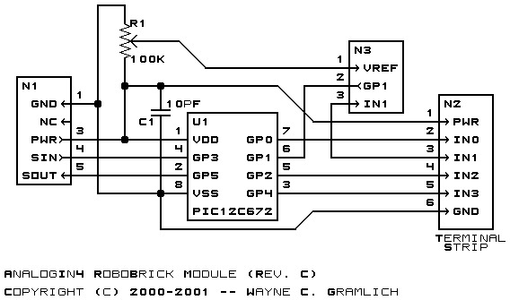
The hardware consists of a circuit schematic and a printed circuit board.
The schematic for the AnalogIn4 RoboBrick is shown below:
The parts list kept in a separate file -- analogin4.ptl.
The printed circuit board files are listed below:
The Analogin4 software is available as one of:
The following Analogin4 test software is available:
The following fabrication issues came up: