This is the Revision A verion of the Compass8 Module. The status of this project is finished.
This document is also available in PDF format.
The Compass8 Module is a Module that can be used to connect to a Dinsmore Instrument Company digital compass. The compass can report the 8 bearings (N, NE, E, SE, S, SW, W, NW.)
A picture of the unpoplulated board is shown below:
I currently only have one of the digital compass modules and it has less than ideal behavior. My compass module works best in an envionment which has some vibration, otherwise the compass is prone to sticking and can be off by as much as 90 degrees. There is some significant hysterisis as rotation is changed; trying to steer a robot straight by aligning the robot with a bearing boundary (e.g. between N and NE) will not yield a very straight course do to this observed hysterisis effect. Of course, I may have a `lemon' module and other people might have different experiences with their moduels. However, if all you want is basic compass bearing, the Dinsmore digital compass module does seem to meet that requirement at a very reasoable cost.
If you want a more accurate compass module, you might want to try the CMPS01 magnetic compass module available at: Robot Electronics.
The basic operation is to send a query to the Compass8 Module to read the 3 bits of bearing data.
The Compass8 Module supports Module Interrupt Protocol. The interrupt pending bit is set whenever the the formula:
B&Mis non-zero, where:
The Compass8 Module supports both the standard shared commands and the shared interrupt commands in addition to the following commands:
Command Send/
ReceiveByte Value Discussion 7 6 5 4 3 2 1 0 Read Bearing Send 0 0 0 0 0 0 0 0 Return bearing bbb (N=000, NE=001, E=010, SE=011, S=100, SW=101, W=110, NW=111) Receive 0 0 0 0 0 b b b Read Interrupt Mask Send 0 0 0 0 0 0 0 1 Return interrupt mask mmmmmmmm (N, NE, E, SE, S, SW, W, NW) Receive m m m m m m m m Read Raw Send 0 0 0 0 0 0 1 0 Return raw data abcd Receive 0 0 0 0 a b c d Set Interrupt Mask Send 0 0 0 0 0 0 1 1 Set interrupt mask to mmmmmmmm (N, NE, E, SE, S, SW, W, NW) Send m m m m m m m m Read Interrupt Bits Send 1 1 1 0 1 1 1 1 Return the interrupt pending bit p and the interrupt enable bit e. Receive 0 0 0 0 0 0 e p Set Interrupt Commands Send 1 1 1 1 0 c c c Set Interrupt Command ccc. Shared Commands Send 1 1 1 1 1 c c c Execute Shared Command ccc.
The hardware consists of a circuit schematic and a printed circuit board.
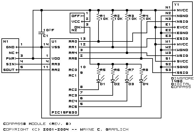
The schematic for the Compass8 Module is shown below:
The parts list kept in a separate file -- compass8.ptl.
The printed circuit board files are listed below:
The Compass8 software is available as one of:
Any fabrication issues that come up are listed here.