This is the Revision A verion of the Debug16 RoboBrick. The status of this project is work in progress.
This document is also available in PDF format.
The Debug16 RoboBrick provides the ability to output 16 8-bit registers using a total of 12 LED's. The first 4 LED's specify which register is being viewed and the remaining 8 LED's specify the register contents. Three buttons are used to increment, decrement, and reset the 4 LED register index.
Many RoboBricks have and additional debugging port that is designed to talk to the Debug16 RoboBrick. Thus, the Debug16 can be used to view the current state of many of the other RoboBricks.
The Debug16 RoboBrick supports the standard shared commands in addition to the following commands:
Command Send/Receive Byte Value Discussion 7 6 5 4 3 2 1 0 Set Index and Low Send 0 0 x x x x l l Set internal index resgister to xxxx and set low order 2 bits of register to ll. Set Index and Low Send 0 0 h h h h h h Set high order bits of internal index register to hhhhhh. Shared Commands Send 1 1 1 1 1 a b c Send shared command abc to RoboBrick.
The hardware consists of a circuit schematic and a printed circuit board.
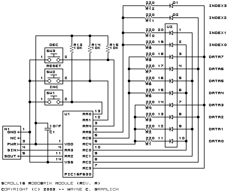
The schematic for the Debug16 RoboBrick is shown below:
The parts list kept in a separate file -- debug16.ptl.
The printed circuit board files are listed below:
The Debug16 software is available as one of:
The Debug16 test suite is available as one of:
Any fabrication issues are listed here.