This is the Revision B verion of the IRDistance8 Module. The status of this project is finished.
This document is also available in PDF format.
The IRDistance8 Module is used to connect up to 8 Sharp® GP2D12 IROD (InfraRed Optical Distance) measuring sensors. The GP2D12 module provides an analog voltage that is proportional to the distance (although not linearly.)
The IRDistance8 Module can enable zero, one or more of the AIROD's. For the ones that are enabled, it continuously reads the distance values. To conserve power, only one AIROD is powered up at a time.
The IRDistance8 Module supports Module Interrupt Protocol for those lines that are being used as inputs. The interrupt pending bit is set whenever the the formula:
L&(~I) | H&I | R&(~P)&I | F&P&(~I)is non-zero, where:
In addition to the common shared commands and the shared interrupt commands, the AnalogIn4 Module supports following commands:
| Command | Send/ Receive |
Byte Value | Discussion | |||||||
|---|---|---|---|---|---|---|---|---|---|---|
| 7 | 6 | 5 | 4 | 3 | 2 | 1 | 0 | |||
| Read 8-bit Analog | Send | 0 | 0 | 0 | 0 | 0 | c | c | c | Return the raw 8-bit analog voltage aaaa aaaa for channel ccc. |
| Receive | a | a | a | a | a | a | a | a | ||
| Read 10-bit Analog | Send | 0 | 0 | 0 | 0 | 1 | c | c | c | Return the raw 10-bit analog voltage aaaa aaaa bb for channel ccc. |
| Receive | a | a | a | a | a | a | a | a | ||
| Receive | b | b | 0 | 0 | 0 | 0 | 0 | 0 | ||
| Read Low Threshold | Send | 0 | 0 | 0 | 1 | 0 | c | c | c | Return the low threshold distance llll llll for channel ccc. |
| Receive | l | l | l | l | l | l | l | l | ||
| Read High Threshold | Send | 0 | 0 | 0 | 1 | 1 | c | c | c | Return the high threshold distance hhhh hhhh for channel ccc. |
| Receive | h | h | h | h | h | h | h | h | ||
| Read High Mask | Send | 0 | 0 | 1 | 0 | 0 | 0 | 0 | 0 | Return and return the high mask hhhh hhhh |
| Receive | h | h | h | h | h | h | h | h | ||
| Read Low Mask | Send | 0 | 0 | 1 | 0 | 0 | 0 | 0 | 1 | Return and return the low mask llll llll |
| Receive | l | l | l | l | l | l | l | l | ||
| Read Raising Mask | Send | 0 | 0 | 1 | 0 | 0 | 0 | 1 | 0 | Return and return the raising mask rrrr rrrr |
| Receive | r | r | r | r | r | r | r | r | ||
| Read Falling Mask | Send | 0 | 0 | 1 | 0 | 0 | 0 | 1 | 1 | Return and return the falling mask ffff ffff |
| Receive | f | f | f | f | f | f | f | f | ||
| Read Servo Steps | Send | 0 | 0 | 1 | 0 | 1 | 0 | 0 | 0 | Return the number of servo steps sssss. |
| Receive | 0 | 0 | 0 | s | s | s | s | s | ||
| Read Sevro Base | Send | 0 | 0 | 1 | 0 | 1 | 0 | 0 | 1 | Return the 16-bit hhhh hhhh llll lll Servo base pulse width (in µS). |
| Receive | h | h | h | h | h | h | h | h | ||
| Receive | l | l | l | l | l | l | l | l | ||
| Read Sevro Increment | Send | 0 | 0 | 1 | 0 | 1 | 0 | 1 | 0 | Return the 16-bit hhhh hhhh llll lll Servo increment pulse width (in µS). |
| Receive | h | h | h | h | h | h | h | h | ||
| Receive | l | l | l | l | l | l | l | l | ||
| Read Sevro Step Delay | Send | 0 | 0 | 1 | 0 | 1 | 0 | 1 | 1 | Return the servo step delay dddd dddd
measured in milliseconds (0 disables servo.) |
| Receive | d | d | d | d | d | d | d | d | ||
| Read Minimum Distance | Send | 0 | 0 | 1 | 1 | 0 | 1 | 0 | 0 | Return minimum distance from the scan dddddddd. |
| Receive | d | d | d | d | d | d | d | d | ||
| Read Minimum Distance Index | Send | 0 | 0 | 1 | 1 | 0 | 1 | 0 | 1 | Return minimum distance index iiiiii. |
| Receive | 0 | 0 | i | i | i | i | i | i | ||
| Read Maximum Distance | Send | 0 | 0 | 1 | 1 | 0 | 1 | 1 | 0 | Return maximum distance from the scan dddddddd. |
| Receive | d | d | d | d | d | d | d | d | ||
| Read Maximum Distance Index | Send | 0 | 0 | 1 | 1 | 0 | 1 | 1 | 1 | Return minimum distance index from the scan iiiiii. |
| Receive | 0 | 0 | i | i | i | i | i | i | ||
| Set Low Threshold | Send | 0 | 1 | 0 | 1 | 0 | c | c | c | Set the low threshold distance for channel ccc to llll llll. |
| Send | l | l | l | l | l | l | l | l | ||
| Set High Threshold | Send | 0 | 1 | 0 | 1 | 1 | c | c | c | Set the high threshold distance for channel ccc to hhhh hhhh. |
| Send | h | h | h | h | h | h | h | h | ||
| Set High Mask | Send | 0 | 1 | 1 | 0 | 0 | 0 | 0 | 0 | Set the high mask to hhhh hhhh. |
| Send | h | h | h | h | h | h | h | h | ||
| Set Low Mask | Send | 0 | 1 | 1 | 0 | 0 | 0 | 0 | 1 | Set the low mask to llll llll. |
| Send | l | l | l | l | l | l | l | l | ||
| Set Raising Mask | Send | 0 | 1 | 1 | 0 | 0 | 0 | 1 | 0 | Set the raising mask to rrrr rrrr. |
| Send | r | r | r | r | r | r | r | r | ||
| Set Falling Mask | Send | 0 | 1 | 1 | 0 | 0 | 0 | 1 | 1 | Set the falling mask to ffff ffff. |
| Send | f | f | f | f | f | f | f | f | ||
| Set Servo Steps | Send | 0 | 1 | 1 | 0 | 1 | 0 | 0 | 0 | Set the number of servo steps to sssss. |
| Send | 0 | 0 | 0 | s | s | s | s | s | ||
| Set Sevro Base | Send | 0 | 1 | 1 | 0 | 1 | 0 | 0 | 1 | Set the servo base pulse width to hhhh hhhh llll lll (a 16-bit number measured in µs). |
| Send | h | h | h | h | h | h | h | h | ||
| Send | l | l | l | l | l | l | l | l | ||
| Set Sevro Increment | Send | 0 | 1 | 1 | 0 | 1 | 0 | 1 | 0 | Set the servo increment pulse width to hhhh hhhh llll lll (a 16-bit number measured in µs). |
| Send | h | h | h | h | h | h | h | h | ||
| Send | l | l | l | l | l | l | l | l | ||
| Set Sevro Step Delay | Send | 0 | 1 | 1 | 0 | 1 | 0 | 1 | 1 | Set the servo step delay dddd dddd
measured in milliseconds (0 disables servo.) |
| Send | d | d | d | d | d | d | d | d | ||
| Read Scan Distance | Send | 1 | 0 | i | i | i | i | i | i | Return the distance dddd dddd for scan position iiiiii. |
| Receive | d | d | d | d | d | d | d | d | ||
| Read Interrupt Bits | Send | 1 | 1 | 1 | 0 | 1 | 1 | 1 | 1 | Return the interrupt pending bit p and the interrupt enable bit e. |
| Receive | 0 | 0 | 0 | 0 | 0 | 0 | e | p | ||
| Set Interrupt Commands | Send | 1 | 1 | 1 | 1 | 0 | c | c | c | Set Interrupt Command ccc. |
| Shared Commands | Send | 1 | 1 | 1 | 1 | 1 | c | c | c | Execute common shared command ccc |
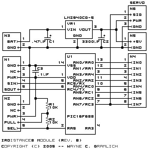
The hardware consists of a circuit schematic and a printed circuit board.
The schematic for the IRDistance8 Module is shown below:
The parts list kept in a separate file -- irdistance8.ptl.
The printed circuit board files are listed below:
The software for the IRDistance8 is listed below:
Any issues that come up will be discussed here.