This is the Revision F version of the LCD32 RoboBrick. The status of this project is work in progress.
This document is also available in PDF format.
The LCD32 module can display a total 4 lines of 16 characters each, of which only 2 lines are visible at a time. The characters are displayed using a 5×7 dot matrix. There is a mechancal switch labeled LINES on the LCD32 module that switches between displaying lines 1-2 and lines 3-4. The LCD32 module is based upon the inexpensive Lumex® LCM-S01602DTR/M 2×16 liquid crystal display (LCD) module available from both Digikey® and Mouser®. The LCD32 module has a small trim potentiometer that allows you adjust the display contrast.
The LCD32 can be used in two ways:
Description Mode Select Master Out Slave Out LCD32 RX (S1) (S0) (N1-5) (N3-4) (U1-5) Master to LCD32 (User Mode) 1 x LCD32 TX (U1-6) x (Master In) (N1-4) Master In (N3-4) Slave to LCD32 (Debug Mode) 0 1 idle (high) Master In (N1-4) Slave In (N3-5) Slave to Master (Debug Mode) 0 0 Slave In (N3-5) Master In (N1-4) idle (high)
The LCD32 module is meant to be used in conjunction with the LCD32Holder (Rev. A) board which carries the actual LCM-201602DTR/M and plugs onto the top of the LCD32 module.
| Command | Send/ Receive |
Byte Value | Discussion | |||||||
|---|---|---|---|---|---|---|---|---|---|---|
| 7 | 6 | 5 | 4 | 3 | 2 | 1 | 0 | |||
| Back Space | Send | 0 | 0 | 0 | 0 | 1 | 0 | 0 | 0 | Move cursor to the left. |
| Line Feed | Send | 0 | 0 | 0 | 0 | 1 | 0 | 1 | 0 | Advance currsor to beginning of next line; clear the next line |
| Form Feed | Send | 0 | 0 | 0 | 0 | 1 | 1 | 0 | 0 | Clear entire display and place cursor at home |
| Carriage Return | Send | 0 | 0 | 0 | 0 | 1 | 1 | 0 | 1 | Return cursor to beginning of line |
| Character 32 to 63 | Send | 0 | 0 | 1 | x | x | x | x | x | Enter the character on the display and advance cursor. |
| Character 64 to 127 | Send | 0 | 1 | x | x | x | x | x | x | Enter the character on the display and advance cursor. |
| Line Set | Send | 1 | 0 | 0 | 0 | 0 | 0 | l | l | Move cursor to line ll |
| Line Clear | Send | 1 | 0 | 0 | 0 | 0 | 1 | l | l | Move cursor to line ll and clear it |
| Cursor Mode Set | Send | 1 | 0 | 0 | 0 | 1 | 0 | v | b | Cursor mode is set (v=1 visible cursor) (b=1 blinking cursor) |
| Cursor Mode Read | Send | 1 | 0 | 0 | 0 | 1 | 1 | 0 | 0 | Read cursor mode (v=1 visible cursor) (b=1 blinking cursor) |
| Receive | 0 | 0 | 0 | 0 | 0 | 0 | v | b | ||
| Character Read | Send | 1 | 0 | 0 | 0 | 1 | 1 | 0 | 1 | Read the current character ccc cccc; advance cursor |
| Receive | 0 | c | c | c | c | c | c | c | ||
| Line Read | Send | 1 | 0 | 0 | 0 | 1 | 1 | 1 | 0 | Read the current line ll |
| Receive | 0 | 0 | 0 | 0 | 0 | 0 | l | l | ||
| Position Read | Send | 1 | 0 | 0 | 0 | 1 | 1 | 1 | 1 | Read the current character position pppp |
| Receive | 0 | 0 | 0 | 0 | p | p | p | p | ||
| Position Set | Send | 1 | 0 | 0 | 1 | p | p | p | p | Move cursor to character position pppp |
| Position Set | Send | 1 | 0 | 1 | 0 | p | p | p | p | Move cursor to character position pppp; clear to end of line |
| Shared Commands | Send | 1 | 1 | 1 | 1 | 1 | c | c | c | Execute shared command ccc. |
The hardware consists of a circuit schematic and a printed circuit board.
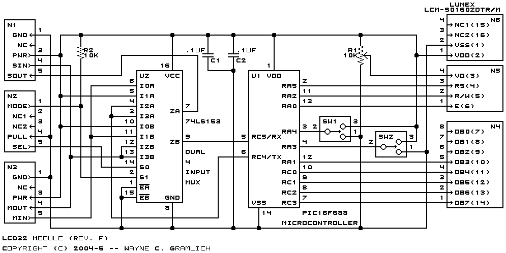
The schematic for the LCD32 RoboBrick is shown below:
The parts list kept in a separate file -- lcd32.ptl.
The printed circuit board files are listed below:
The LCD32 software is available as one of:
The fabrication issues will be listed here.