This is the construction instructions for the
Light4 (rev. B) RoboBrick. The status of this project is
work in progress.
Light4 RoboBrick (Revision B) Construction
The instruction steps for building the Light4
(Rev. B) RoboBrick are listed below:
-
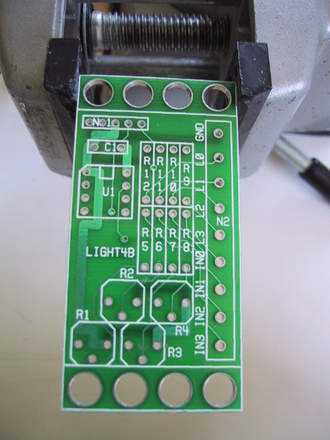
Orient the board vertically. By convention
the upper edge is north, the lower edge is
south, the left edge is west and the right
edge is east. Orient the board so that N1
is in the north west corner.
[step1.jpg]
-
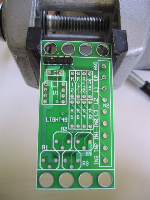
Take a 1×5 male header and using
some diagonal cutters, snip off pin 2 marked
with an `X' in the the diagram below:
Insert the header into N1 with pin 1 to
the west. Solder one pin and verify that
the header is flat on the board. If not,
re-heat the solder pin and reposition the
header until it is flat and vertical on
the board. Solder the remaining 9 pins.
[step2.jpg]
-
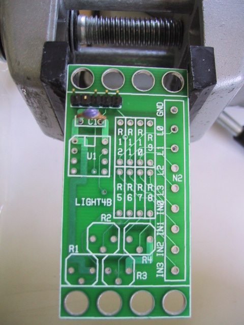
Find a 10pF capacitor and insert it into C1.
Spread the leads a little so it will not
fall out. Turn the board over and solder
one lead. Turn the board over again and
verify that the capacitor is still positioned
vertically. If not, re-heat the lead you
just soldered an reposition the capacitor.
Now solder the remaining lead. Snip off
the excess capacitor leads.
[step3.jpg]
-
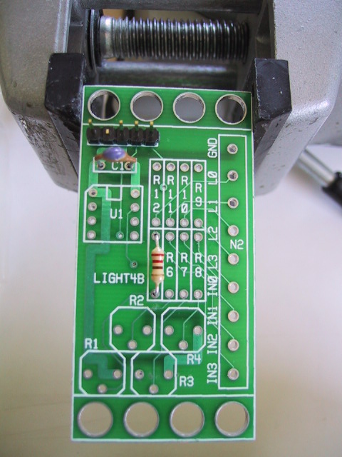
Find a 2K resistor (Red Black Red).
If you can not find a 2K resistor, look
for a 2.2K resistor (Red Red Red) instead.
Bend both leads 90 degrees so that the
resistor comfortably fits into R5.
Just for consistency, place the red band
up. (Resistors are symmetric, so there is
no damage done if you install the resistor
with the red band down.) Turn the board over,
and spread the leads a little to keep it from
coming out. Solder one lead. Now turn it over
to verify that the position is acceptable.
If not, re-heat the lead you just soldered and
get it positioned to your liking. Solder in
the remaining lead. Snip off the excess leads
sticking out the back.
[step4.jpg]
-
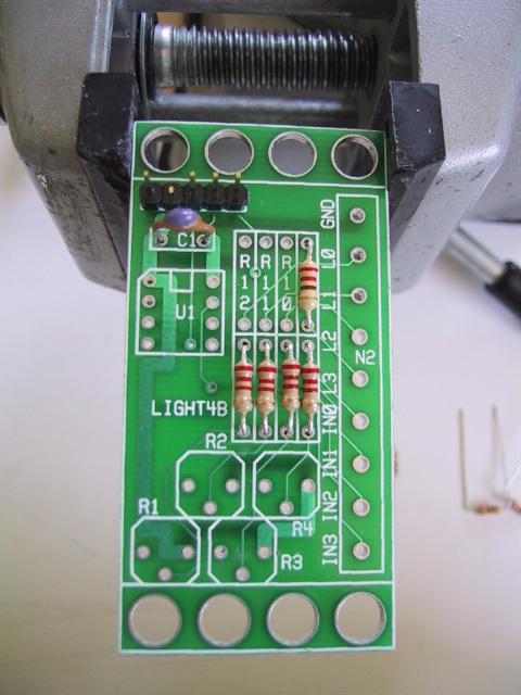
Repeat the preceding instruction with three
more of the same resistors and insert them
into R6 through R8. Solder them as in
the preceding instruction.
[step5.jpg]
-
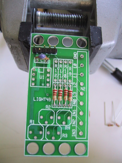
Find a 220 Ohm resistor (Red Red Brown)
and install it into position R9 and solder
as before.
[step6.jpg]
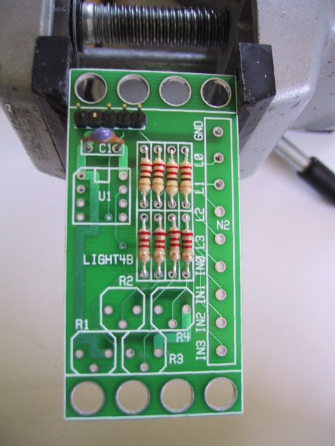
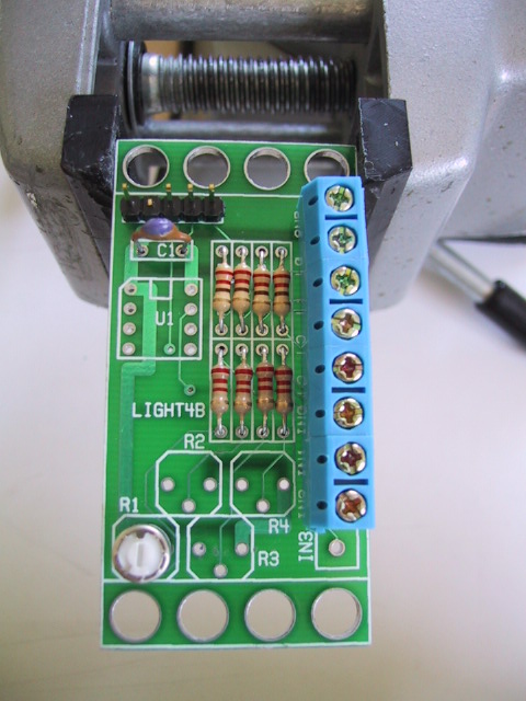
-
Install the remaining three 220 Ohm resistors in
positions R10 through R12.
[step7.jpg]
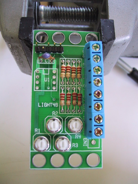
-
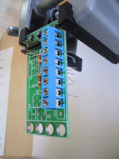
Find the 9-terminal terminal strip and insert
it into N2. If all you can find is some 3-terminal
strips, a 9-terminal strip can be assembled from
three 3-terminal strip by sliding them together.
Make sure that the wire holes point towards the
east. Solder in 1 pin, verify position, and
solder the remaining pins. (Note: this picture
was taken with an 8-terminal terminal strip;
you should use a 9-terminal terminal strip instead.)
[step8.jpg]
-
Find a 10K Ohm trim potentiometer. Insert it
into R1 so that the leads go in straight.
Solder one lead, verify that it is flat on
the board, solder in the remaining two pins
and snip off any excess leads.
[step9.jpg]
-
Perform the previous instruction on the remaining
three potentiometers and install them into
R2 through R4.
[step10.jpg]
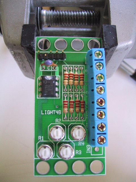
-
Find the pre-programmed PIC12C672 and insert
it into U1 with pin 1 pointing up. Solder
in 1 pin, verify position, and solder in
the remaining pins. The picture highlights
the notch in U1 with some white marker.
[step11.jpg]
The assembly of the Light4 (Rev. B) RoboBrick is
complete.
Copyright (c) 2002 by
Wayne C. Gramlich.
All rights reserved.