This is the revision B version of the MicroBrain8 module. The status of this project is finished.
This document is also available as a PDF document.
The MicroBrain8 module is a controller module that can control up to 8 sensor or actuator modules. It is controlled by any microcontroller that is pin compatible with the Parallax a Basic Stamp 2® It has two terminals that can be connect to a battery between 6 and 9 volts. It has an on board 5 volt voltage regulator to provide power to the other sensor and actuator modules. The is a connector that can be connected to a DB9 connector and used to communicate with a controlling PC via RS-232 voltage levels.
We may eventually put a few examples of programming the MicroBrain8 here. Basically, it is programmed using the Parallax Basic for the Basic Stamp 2.
    ' Even numbered pins inputs and odd number pins are outputs.
    ' (Remember for the BS2, 1=output and 0=input.)
    dirs = $aaaa

    ' Set all outputs to high:
    high 1
    high 3
    high 5
    high 7
    high 9
    high 11
    high 13
    high 15

    ' To copy a Switch8-B (on N2) to LED10-B (on N1):
    switches var byte
    loop:
	' Send command 0 (Read switches) to Switch8-B:
	serout 11, 396, [0]
	' Receive the switch readings from Switch8-B:
	serin 10, 396, [switches]
	' Send switch values to LED10-B:
	serout 9, 396, [switches]
	goto loop
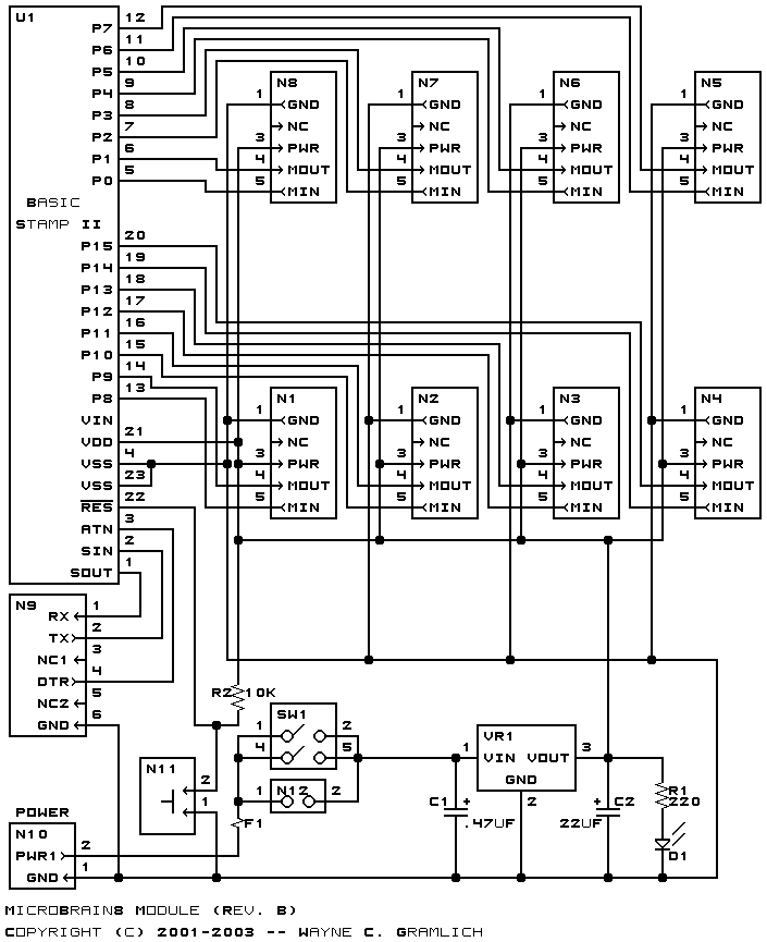
Connector Input Output N1 (Top) P8 P9 N2 P10 P11 N3 P12 P13 N4 P14 P15 N5 P6 P7 N6 P4 P5 N7 P2 P3 N8 (Bottom) P0 P1
The hardware consists of a circuit schematic and a printed circuit board.
The schematic for the MicroBrain8 RoboBrick is shown below:
The parts list kept in a separate file -- microbrain8.ptl.
The printed circuit board files are listed below:
The construction instructions are kept in a separate file document to be a little more printer friendly.
The software for the MicroBrain8 is developed by the user.
Any fabrication issues that come up will be listed here.