This is the Revision A verion of the Motor3 RoboBrick. The status of this project is work in progress.
This document is also available as a PDF document.
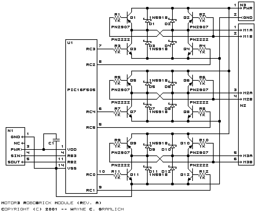
The Motor3 RoboBrick allows for control of up to three small DC motors via pulse width modulation. The motor voltage input can range from 1 volt to 24 volts.
No programming specification yet.
The hardware consists of a circuit schematic and a printed circuit board.
The schematic for the Motor3 RoboBrick is shown below:
The parts list kept in a separate file -- motor3.ptl.
The printed circuit files are listed below:
There is no software yet.
Any fabrication issues are listed here.