This is the Revision A verion of the Pic16F876 RoboBrick. The status of this project is that it has been replaced by the PIC876Hub10 RoboBrick.
This document is also available as a PDF document.
The PIC16F876 RoboBrick is a master RoboBrick for controlling a robot. It is based on the PIC16F876 from MicroChip®.
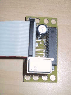
A picture of the PIC16F876 RoboBrick is shown below:
One nice feature of the PIC16F876 is that it can write into its program memory without requiring any additional voltages or hardware. An initial boot loader will be placed in upper memory. This boot loader will talk to the development system via a link RoboBrick like the Tether RoboBrick. The development system will download the programs over the link and the boot loader will store the program into memory and execute it. If the program crashes, the standard watchdog timer on PIC16F876 will transfer control back to the boot loader.
The PIC16F876 is initially programmed with a boot loader that allows other programs to be downloaded and executed. The boot loader lives in upper memory and provides a way of downloading a program to be executed in lower memory. In addition to boot loading, there are some additional facilities for examining and setting memory for debugging purposes.
Upon startup, the boot loader selects port 0 of the hub, prints out the RoboBrick name and version, followed by a prompt as shown below:
    RoboBrick PIC16F876-A Version 1.0
    >
There are only five supported commands:
Upon receiving the first command that starts with a `:', prompts are supressed until the done command is received. This allows a user to `throw' a .hex file at the boot loader using a terminal emulator. Under no circumstances will the boot loader overwrite either itself, the configuration word, or the first word of program memory (which is a GOTO instruction to the boot loader.)
- :
- The command starts witha colon (`:').
- LL
- LL is a two digit hex number that specifies how many bytes of data are being programmed. Remember, it takes two bytes to program a single word of program memory.
- AAAA
- AAAA is four digit hex number that specifies the `byte address' at which to program the first byte. The byte address is word address shifted over by 1 bit.
- CC
- CC is a command of either 00 or 01. 00 specifies load and 01 specifies done.
- DD ...
- DD is sequence of LL bytes of data to be programmed. The low order program byte comes before the high order program byte.
- SS
- SS is a two's complement checksum of all of the bytes that make up the command line.
The hardware consists of a circuit schematic and a printed circuit board.
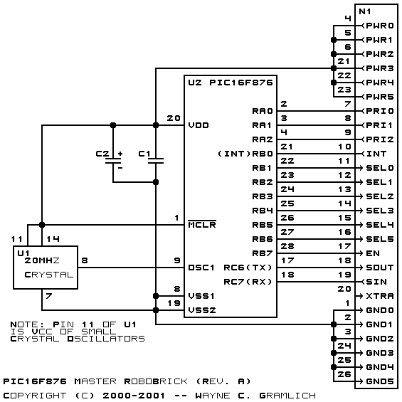
The schematic for the Pic16F876 RoboBrick is shown below:
The parts list kept in a separate file -- pic16f876.ptl.
The printed circuit files are listed below:
The software for the PIC16F876 will eventually become quite sophisticated. But for starters it will be little more than testing software for whole system. The files are:
The following issues came up on the revision A version of the PIC16F876 RoboBrick: