This is the Revision A version of the PIC876Hub10 RoboBrick. The status of this project is work in progress.
This document is also available as a PDF document.
The PIC876Hub10 RoboBrick is a master RoboBrick that can control up to N slave RoboBricks. It uses a PIC16F876 microcontroller from MicroChip®. One of the hub ports can be connected to a communications RoboBrick to provide the ability to talk to the development platform.
There is a three terminal connector, one for ground and the other two for power. One power connector is connected to a standard 3-terimal 5 volt regulator to provide 5 volts to the slave RoboBricks. The other power regulator is only sensed for voltage level. The microcontroller has a built in analog to digital converter that allows it to sense the power level on both power terminals. When the power goes below a preset level, the robot platform can choose to enter a `hungry' behavior mode.
There is no programming specification for the PIC876Hub10 RoboBrick yet.
The hardware consists of a circuit schematic and a printed circuit board.
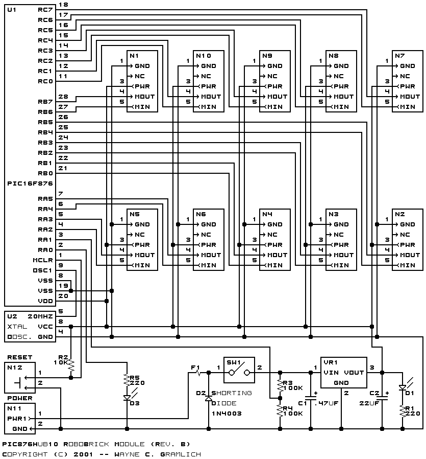
The schematic for the PIC876Hub10 RoboBrick is shown below:
The parts list kept in a separate file -- pic876hub10.ptl.
The printed circuit board files are listed below:
There is no software for this RoboBrick yet.
The following fabrication issues came up: