This is the revision B version of the PICBrain11 module. The status of this project is finished.
This document is also available as a PDF document.
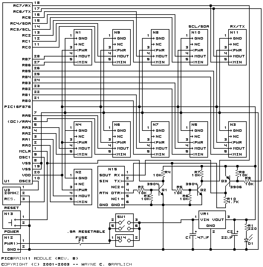
The PICBrain11 module can control up to 11 sensor and actuator modules. It uses a PIC16F876 microcontroller from MicroChip®. There is on board RS-232 level conversion circuitry so that the PICBrain11 can be directly connected to a PC serial port. There is an on-board 5 volt regulator for supplying regulated voltage to other sensor and actuator modules.
There is no programming specification for the PICBrain11 yet.
The hardware consists of a circuit schematic and a printed circuit board.
The schematic for the PICBrain11 module is shown below:
The parts list kept in a separate file -- picbrain11.ptl.
The printed circuit board files are listed below:
DB9 Direction N15 PIC Label Pin Label Pin Label Pin RX 2 <== SOUT 1 RC6/TX 17 TX 3 ==> SIN 2 RC7/RX 18 DTR 4 ==> ATN 4 MCLR 1 GND 5 <=> GND 6 VSS 8,19 RTS 7 Short 7 to 8 DSR 8
There is no software for this module yet.
The following fabrication issues came up: