This is the Revision b version of the ProtoPIC RoboBrick. The status of this project is work in progress.
This document is also available as a PDF document.
The ProtoPIC RoboBrick is a RoboBrick with a socket for either an 8-pin PIC (e.g. PIC12C509, PIC12C672, etc) or a 14-pin PIC16C505. The rest of the board has plated through holes on a .1 inch grid for attachining other components.
For the 8-pin PIC's, a jumper selects whether the SIN pin (N1) is connected to GP3 or GP4. GP5 is connected to SOUT (N1).
The hardware consists of a circuit schematic and a printed circuit board.
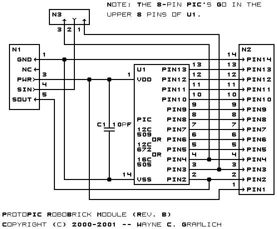
The schematic for the Protopic RoboBrick is shown below:
The parts list kept in a separate file -- protopic.ptl.
The printed circuit files are listed below:
Any fabrication issure are listed here.