This is the Revision B verion of the Reckon2 Module. The status of this project is work in progress.
This document is also available in PDF format.
The Reckon2 module is used to manuver a robot. It can contol two motors in "differential steering" mode. Each motor needs to have a shaft encoder with a quadrature output. If there is enough resolution on the shaft encoder and the wheels are not too "squishy", it is possible to keep pretty accurate track of a robot's location and bearing using deduced reckoning. (Note: deduced reckoning is abbreiated as ded. reckoning and is now frequently refered to by the term "dead reckoning".)
There is no programming yet.
The hardware consists of a circuit schematic and a printed circuit board.
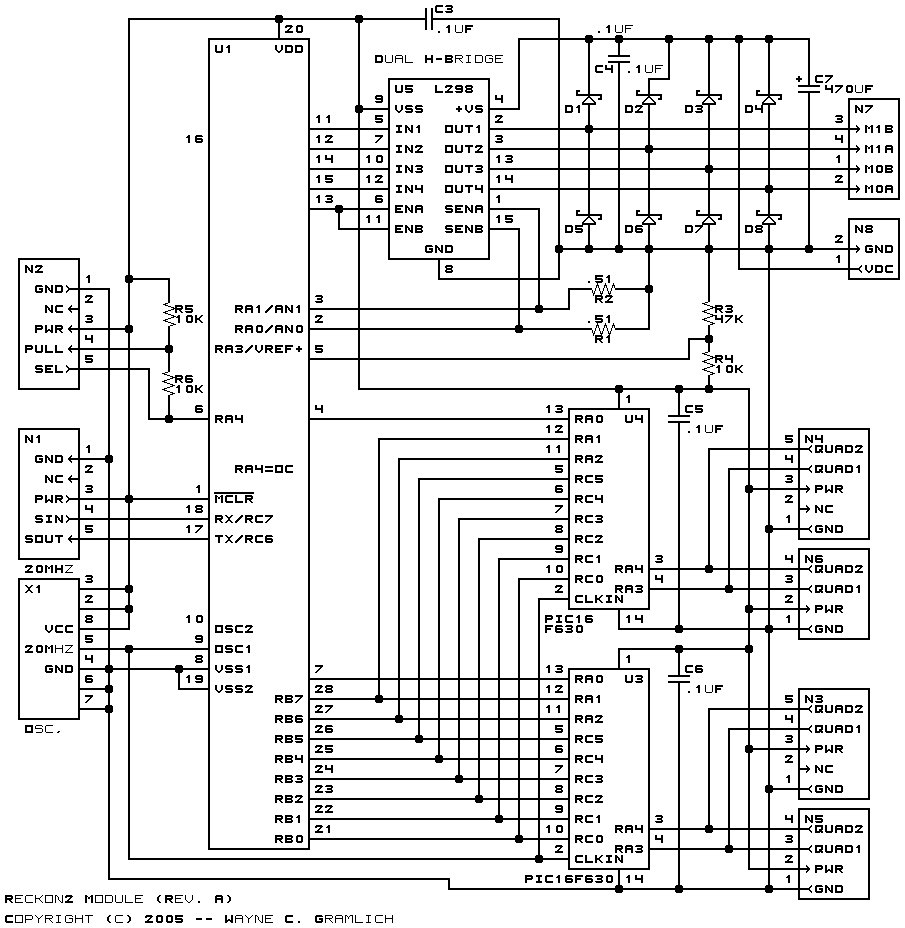
The schematic for the Reckon2 Module is shown below:
The parts list kept in a separate file -- reckon2.ptl.
The printed circuit board files are listed below:
There is no software yet.
The following fabrication issues need to be addressed: