This is the Revision B version of the Servo4 module. The status of this project is that it has been replaced by the Revision C version.
This document is also available as a PDF document.
The Servo4 module allows for the control of up to 4 hobby grade servos.
The Servo4 module can independently control up to 4 servos. Each servo has 1) an enable bit and 2) a current position. The position is represented as an 8-bit number. Some experimentation is needed to determine how the 8-bit numbers correspond to actual servo positions. All servos are initialized to have the enable flags off.
The Servo4 commands are summarized in the table below:The Servo4 module does not know the minimum and maximum extent for each servo. This has to be determined by experimentation.
Command Send/
ReceiveByte Value Discussion 7 6 5 4 3 2 1 0 Set High Send 0 0 h h h h s s Set high order 4 bits of servo ss to hhhh and set the remaining 4 low order bits to zero. .Set Low Send 0 1 l l l l s s Set the low order 4 bits of servo ss position to llll. Increment Send 1 0 0 i i i s s Add iii to the position of servo ss. Decrement Send 1 0 1 d d d s s Subtract ddd from the position of servo ss. Set Position/Enable Send 1 1 0 0 0 e s s Select servo ss and set its position to ppppppp and enable flag to e. Send p p p p p p p p Set Enable Flag Send 1 1 0 0 1 e s s Select servo ss and set its enable flag to e. Read Position Send 1 1 0 1 0 0 s s Return the current position pppppppp for servo ss. Receive p p p p p p p p Read Enable Send 1 1 0 1 0 1 s s Return the enable bit e for servo ss. Receive 0 0 0 0 0 0 0 e Read Enables Send 1 1 0 1 1 0 0 0 Return the enable flags eeee for all four servos. Receive 0 0 0 0 e e e e Set Enables Send 1 1 0 1 1 0 0 1 Set enable flags for all four servos to eeee. Send 0 0 0 0 e e e e Shared Commands Send 1 1 1 1 1 c c c Execute shared command ccc.
The hardware consists of a circuit schematic and a printed circuit board.
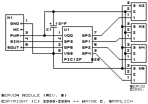
The schematic for the Servo4 module is shown below:
The parts list kept in a separate file -- servo4.ptl.
The printed circuit board files are listed below:
The Servo4 software is available as one of:
The following fabrication issues came up: