This is the Revision J version of the Servo4 module. The status of this project is finished.
This document is also available as a PDF document.
The Servo4 module allows for the control of up to 4 hobby grade servos. It can be configured as follows:
Up to four RC servos are connected to connectors N2 (servo 0) through N5 (servo3). Each connector has the following pin definitions:
On many servos, the black wire is the ground wire. You will have to check you servo documentation to be absolutely sure though.
Pin Location Description 1 Right Servo control signal (varies between 0 and 5 volts) 2 Center 5 Volts 3 Left Ground (0 Volts)
The connection to the controlling module occurs via N1 in the upper left corner.
Power for the servos comes from N9, the blue two terminal connector in the upper right corner. Connect a power source of 6-9 volts to connector N9, where the upper terminal is the positive terminal ('+') and the the lower terminal is negative ('-').
The hardware configuration for each mode is summarized in the table below:
Mode Jumpers Trim Pots LED N7 N8 N10 R4 R5 D1 Pure Servo Mode Right (2-3) Right (2-3) Down (2-3) Unused Unused Off Differential Steering Mode Left (1-2) Left (1-2) Down (2-3) Servo 0 Stop Servo 1 Stop Off Differential Steering Calibration Mode Left (1-2) Left (1-2) Up (1-2) Servo 0 Stop Servo 1 Stop On
In differential steering calibration mode, N10 is jumpered upward and it causes yellow LED D1 to light. It causes both servos 0 and 1 to be enabled. The value of trim pot R5 to be sent to servo 0 and trim pot R6 to be sent to servo 1. The purpose of calibration mode is to allow you to adjust the two modified servos that are connected to servo 0 and servo 1 and adjust them until they stop rotating. This frees the programmer from having to experiment to find the `position' number for each servo that corresponds to each servo being motionless. The values of the stop value are read out using the Read Current Draw command for servo 2 and 3.
The Servo4 module can independently control up to 4 servos. Servo position is strictly a function of pulse width. The user can configure the Servo4 emit a wide range of pulse widths from 1µS to 4095µS. Most servos run up against a mechanical limit on the low end around 400&mirco;S and the other mechanical limit around 2600µS. Each servo has computes width of its output pulse using following formula:
W = (BH * 256) + BL + P * S/16 + Fwhere
In addition, each servo has an enable bit. Since so many people use modified servos for robot drive gear motors, the servos are initialized to the off position.
The Servo4 commands are summarized in the table below:
The Servo4 module does not know the minimum and maximum extent for each servo. This has to be determined by experimentation.
Command Send/
ReceiveByte Value Discussion 7 6 5 4 3 2 1 0 Set Base Low Send 0 0 0 0 0 0 s s Set the low 8-bits of the minimum pulse width time (measured in µS) to llll llll. Send l l l l l l l l Set Base High Send 0 0 0 0 0 1 s s Set the high 8-bits of the minimum pulse width time (measured in µS) for servo ss to hhhh hhhh. Send h h h h h h h h Set Position Send 0 0 0 0 1 0 s s Set the position for servo ss to pppp pppp. Send p p p p p p p p Set Scale Send 0 0 0 0 1 1 s s Set the scale for servo ss to iiii.ffff (i.e. iiii + ffff/16.) Send i i i i f f f f Read Base Low Send 0 0 0 1 0 0 s s Read the low 8-bits of the minimum pulse width time (measured in µS) as llll llll. Send l l l l l l l l Read Base High Send 0 0 0 1 0 1 s s Read the high 8-bits of of the minimum pulse width (measured in µS) for servo ss as hhhh hhhh. Send h h h h h h h h Read Position Send 0 0 0 1 1 0 s s Read the position for servo ss as pppp pppp. Send p p p p p p p p Read Scale Send 0 0 0 1 1 1 s s Read scale for servo ss as iiii.ffff (i.e. iiii + ffff/16.) Send i i i i f f f f Set High Send 0 1 h h h h s s Set high order 4 bits of servo ss to hhhh and set the remaining 4 low order bits to zero. .Set Low Send 1 0 l l l l s s Set the low order 4 bits of servo ss position to llll. Set Enable and Position Send 1 1 0 0 0 e s s Select servo ss and set its position to ppppppp and enable flag to e. Send p p p p p p p p Set Enable Flag Only Send 1 1 0 0 1 e s s Select servo ss and set its enable flag to e. Read Position Send 1 1 0 1 0 0 s s Return the current position pppppppp for servo ss. Receive p p p p p p p p Read Enable Send 1 1 0 1 0 1 s s Return the enable bit e for servo ss. Receive 0 0 0 0 0 0 0 e Read Enables Send 1 1 0 1 1 0 0 0 Return the enable flags eeee for all four servos. Receive 0 0 0 0 e e e e Set Enables Send 1 1 0 1 1 0 0 1 Set enable flags for all four servos to eeee. Send 0 0 0 0 e e e e Read Current Draw Send 1 1 0 1 1 1 s s Return the aaaaaaaa current draw for servo ss. Receive a a a a a a a a Shared Commands Send 1 1 1 1 1 c c c Execute shared command ccc.
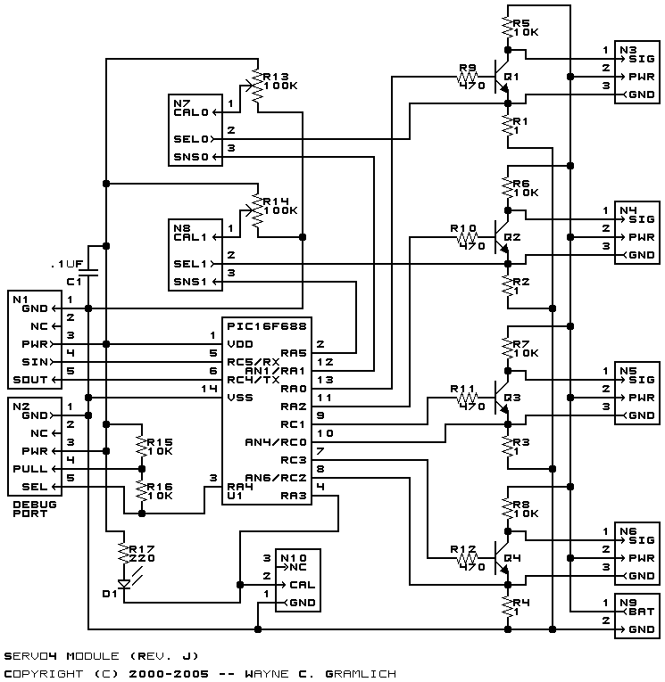
The hardware consists of a circuit schematic and a printed circuit board.
The schematic for the Servo4 module is shown below:
The parts list kept in a separate file -- servo4.ptl.
The printed circuit board files are listed below:
The Servo4 software is available as one of:
The following issues need to be dealt with: