This is the Revision A version of the Shaft2 RoboBrick. The status of this project is work in progress.
This document is also available as a PDF document.
The Shaft2 RoboBrick can keep track of the quadrature encoding of 2 shaft encoders.
For quadrature encoding, two sensors are used to sense the shaft position. The sensors are positioned 90 degrees out of phase with one another so that the two sensors generate states of the form 00 - 01 - 11 - 10 - 00 ... in the clockwise direction and 00 - 10 - 11 - 01 - 00 ... in the counter-clockwise direction. Each time the state transitions clockwise, a 16-bit counter is incremented; conversely, each transition in the counter-clockwise direction decrements the 16-bit counter.
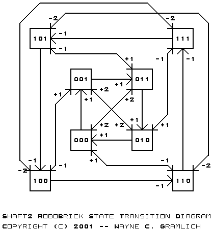
The Shaft2 RoboBricks actually use an eight state transition diagram as shown below:
The first bit is the direction (1=counter-clockwise and 0=clockwise.) The next two bits are the sensor bits. By keeping track of the direction bit as part of the state transisition diagram, it is possible to do something intelligent if somehow the shaft is spinning so fast that it skips a state (e.g. 00 - 11 or 01 - 10.) In this case, the direction bit is used to determine whether to increment or decrement the counter by 2.
There are two shafts named shaft 0 and shaft 1. There is an unsigned sixteen bit counter associated with each shaft. Each shaft has both a 16-bit low and a 16-bit high threshold register used for generating interrupts. The interrupt pending bit is set whenever the shaft counter exceeds the range specified by the 16-bit high and low counters. The interrupt pending flag is computed as follows:
I = S0<L0 | S0>H0 | S1<L1 | S1>H1where
In addition to the common shared commands and the interrupt protocol, the Shaft2 RoboBrick supports the commands summarized in the table below:
Command Send/
ReceiveByte Value Discussion 7 6 5 4 3 2 1 0 Read Shaft Send 0 0 0 0 0 0 0 s Read shaft s and respond with 16-bit counter value hhhhhhhh llllllll Receive h h h h h h h h Receive l l l l l l l l Read Shaft Low Send 0 0 0 0 0 0 1 s Return low order 8-bits llllllll of shaft s Receive l l l l l l l l Set Shaft Send 0 0 0 0 0 1 0 s Set counter for shaft s to hhhhhhhh llllllll Receive h h h h h h h h Receive l l l l l l l l Set Shaft Low Send 0 0 0 0 0 1 1 s Set low 8-bits for shaft s to llllllll Receive l l l l l l l l Increment Shaft Send 0 0 0 0 1 0 0 s Increment counter for shaft s Decrement Shaft Send 0 0 0 0 1 0 1 s Decrement counter for shaft s Clear Shaft Send 0 0 0 0 1 1 0 s Clear counter for shaft s Set High Threshold Send 0 0 0 1 0 0 0 s Set high threshold for shaft s to hhhhhhhh llllllll (default 01111111 11111111) Send h h h h h h h h Send l l l l l l l l Set Low Threshold Send 0 0 0 1 0 0 1 s Set low threshold for shaft s to hhhhhhhh llllllll (default 10000000 00000000) Send h h h h h h h h Send l l l l l l l l Read High Threshold Send 0 0 0 1 0 1 0 s Read and return high threshold for shaft s as hhhhhhhh llllllll Receive h h h h h h h h Receive l l l l l l l l Read Low Threshold Send 0 0 0 1 0 1 1 s Read and return high threshold for shaft s as hhhhhhhh llllllll Receive h h h h h h h h Receive l l l l l l l l Read Interrupt Bits Send 1 1 1 0 1 c c c Read interrupt enable bit e and interrupt pending bit p. Receive 0 0 0 0 0 0 e p Set Interrupt Bits Send 1 1 1 1 0 c c c Execute set interrupt bits command ccc Shared Commands Send 1 1 1 1 1 c c c Execute common shared command ccc
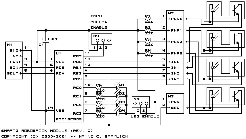
The hardware consists of a circuit schematic and a printed circuit board.
The schematic for the Shaft2 RoboBrick is shown below:
The parts list kept in a separate file -- shaft2.ptl.
The printed circuit board files are listed below:
The Shaft2 software is available as one of:
The Shaft2 test suite is available as one of:
Any fabrication issues are listed here.