This is the Revision A version of the Stepper1 RoboBrick. The status of this project is that it has been replaced by the revision B version.
This document is also available as a PDF document.
The Stepper1 RoboBrick allows for the control of 1 small bipolar or unipolar stepper motor.
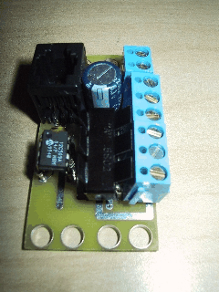
A picture of a Stepper1-A RoboBrick is shown below:
The Stepper1 RoboBrick is used to control a single bipolar or unipoloar stepper motor. There are a number of variables inside the Stepper1 RoboBrick:
There are three wave tables:
Wave drive is the easiest to understand since it only activates one coil at a time.
Wave Drive LSB's A B C D 1 0 0 0 1 0 0 0 0 1 0 1 0 0 1 0 0 0 1 0 1 1 0 0 0 1
Two phase drive provides double the torque over Wave Drive (at double the power consumption.) This is accomplished by always having two coils activated at the same time.
Two Phase LSB's A B C D 1 0 0 0 1 1 0 0 0 1 0 1 1 0 1 0 0 0 1 1 1 1 1 0 0 1
Half step mode provides twice the resolution by alternating between activating only one coil and activating two coils. When both coils are on, the power consumption (and torque) is twice that of when only one coil is on.
Half Step LSB's A B C D 2 1 0 0 0 0 1 0 0 0 0 0 1 1 1 0 0 0 1 0 0 1 0 0 0 1 1 0 1 1 0 1 0 0 0 0 1 0 1 0 1 0 0 1 1 1 1 0 0 0 0 1 1 1 1 1 0 0 1
The simplest usage of the Stepper1 RoboBrick is to set the wave table and the slow rate. All rates are measured in units of ticks which are .139 milliseconds (= 1/(3 × 2400)) long. The slow rate specifies the number of ticks between each step. The desired position can be increased to cause stepping to occur in a clockwise direction and decreased to cause counter-clockwise stepping.
In order to improve slew rates, the user can specify some additional variables to support speed ramp up and ramp down. This involves specifying a maximum step rate, a ramp rate, and ramp amount. The maximum step rate and the ramp amount are measured in ticks (.139ms) and the ramp rate is measured in steps.
For example, suppose a stepper motor has a slow step rate of 100 ticks (= 13.9ms) and a fast step rate of 50 ticks (6.9ms). If it can accellerate by 2 ticks every third step, the ramp rate is set to 3 and the ramp amount is set to 4.
There is a complement mask that is used to invert specific bits of the output value. A power down bit is used to power down the stepper coils when the stepper motor is not moving.
The Stepper1 RoboBrick implements the RoboBrick Interrupt Protocol. The interrupt pending bit is set whenever the stepper motor is not being moved. {This may change.}
The Stepper1 RoboBrick commands are summarized in the table below:
Command Send/
ReceiveByte Value Discussion 7 6 5 4 3 2 1 0 Increment Desired Send 0 0 0 i i i i i Increment Desired Counter by iiiii. Decrement Desired Send 0 0 1 d d d d d Increment Desired Counter by ddddd. Set Desired High Send 0 1 0 0 0 0 0 0 Set high order 8-bits of desired counter to hhhhhhhh Send h h h h h h h h Set Desired Low Send 0 1 0 0 0 0 0 1 Set high order 8-bits of desired counter to llllllll and start stepping. Send l l l l l l l l Set Current High Send 0 1 0 0 0 0 1 0 Set high order 8-bits of current counter to hhhhhhhh Send h h h h h h h h Set Current Low Send 0 1 0 0 0 0 1 1 Set high order 8-bits of current counter to llllllll Send l l l l l l l l Set Slow Rate Send 0 1 0 0 0 1 0 0 Set slow step rate to ssssssss. Send s s s s s s s s Set Fast Rate Send 0 1 0 0 0 1 0 1 Set fast step rate to ffffffff. Send f f f f f f f f Set Ramp Rate Send 0 1 0 0 0 1 1 0 Set ramp step rate to ffffffff. Send r r r r r r r r Set Ramp Amount Send 0 1 0 0 0 1 1 1 Set ramp amount to aaaaaaaa. Send a a a a a a a a Read Desired High Send 0 1 0 0 1 0 0 0 Read high order 8-bits of desired counter hhhhhhhh. Receive h h h h h h h h Read Desired Low Send 0 1 0 0 1 0 0 1 Read low order 8-bits of desired counter to llllllll. Receive l l l l l l l l Read Current High Send 0 1 0 0 1 0 1 0 Read high order 8-bits of current counter hhhhhhhh Receive h h h h h h h h Read Current Low Send 0 1 0 0 1 0 1 1 Read high order 8-bits of current counter to llllllll Receive l l l l l l l l Read Slow Rate Send 0 1 0 0 1 1 0 0 Read slow step rate ssssssss. Receive s s s s s s s s Read Fast Rate Send 0 1 0 0 1 1 0 1 Read fast step rate ffffffff. Receive f f f f f f f f Read Ramp Rate Send 0 1 0 0 1 1 1 0 Read ramp rate rrrrrrrr. Receive r r r r r r r r Read Ramp Amount Send 0 1 0 0 1 1 1 1 Read ramp amount aaaaaaaa. Receive a a a a a a a a Set Complement Mask Send 0 1 0 1 c c c c Set complement mask to cccc. Set Wave Table Send 0 1 1 0 0 0 w w Set wave table to ww. Set Denergize Bit Send 0 1 1 0 0 1 0 e Set the deneergize bit to e. Read Denergize Bit Send 0 1 1 0 0 1 1 0 Read the deneergize bit to e. Receive 0 0 0 0 0 0 0 e Read Wave Table Send 0 1 1 0 0 1 1 1 Read wave table ww. Receive 0 0 0 0 0 0 w w Set Desired Send 0 1 1 0 1 0 0 0 Set desired counter to hhhhhhhh llllllll and start stepping. Send h h h h h h h h Send l l l l l l l l Set Current Send 0 1 1 0 1 0 0 1 Set current counter to hhhhhhhh llllllll. Send h h h h h h h h Send l l l l l l l l Read Desired Send 0 1 1 0 1 0 1 0 Read desired counter hhhhhhhh llllllll. Receive h h h h h h h h Receive l l l l l l l l Read Current Send 0 1 1 0 1 0 1 1 Read current counter hhhhhhhh llllllll. Receive h h h h h h h h Receive l l l l l l l l Read Complement Mask Send 0 1 1 0 1 1 0 0 Read complement mask cccccccc Receive c c c c c c c c Reset Send 0 1 1 0 1 1 0 1 Emergency Reset Stop Send 0 1 1 0 1 1 1 0 Immediately ramp the stepper motor to a stop. Read Interrupt Bits Send 1 1 1 0 1 1 1 1 Return the interrupt pending bit p and the interrupt enable bit e. Receive 0 0 0 0 0 0 e p Set Interrupt Commands Send 1 1 1 1 0 c c c Set Interrupt Command ccc. Shared Commands Send 1 1 1 1 1 c c c Execute common shared command ccc
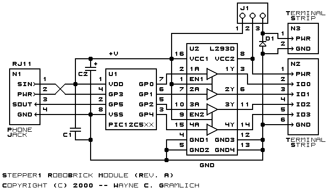
The hardware consists of a circuit schematic and a printed circuit board.
The schematic for the Stepper1 RoboBrick is shown below:
The parts list kept in a separate file -- stepper1.ptl.
The Stepper1 software is available as one of:
The following issues have come up: