This is the Revision A version of the Threshold4 RoboBrick. The status of this project is that it has been replaced by the Light4 RoboBrick.
This document is also available as a PDF document.
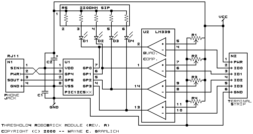
The Threshold4 RoboBrick provides four voltage comparators to convert 4 analog input voltages into four bits of 1 or 0. There are four trim potentiometers that are used to set a threshold voltage between 0 and 5 volts for each of the four voltage comparators. To aid in setting the trim potentiometers, the outputs of the voltage comparators are sent to four LED's. The resulting 4 binary bits of data are available for querying.
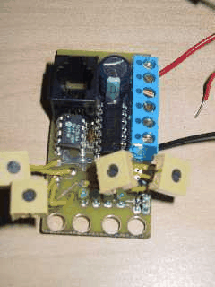
The picture below shows the Threshold4A RoboBrick:
The basic Threshold4 RoboBrick operation is to send a query to the module to read the 4 bits of data. The programmer can download a complement mask to cause any of the bits to be complemented prior to reading.
The Threshold4 RoboBrick supports RoboBrick Interrupt Protocol. The interrupt pending bit is set whenever the the formula:
L&(~I) | H&I | R&(~P)&I | F&P&(~I)]is non-zero, where:
The Threshold4 commands are summarized in the table below:
Command Send/
ReceiveByte Value Discussion 7 6 5 4 3 2 1 0 Read Inputs Send 0 0 0 0 0 0 0 0 Return input values abcd (after XOR'ing with complement mask) Receive 0 0 0 0 a b c d Read Complement Mask Send 0 0 0 0 0 0 0 1 Return complement mask cccc Receive 0 0 0 0 c c c c Read High Mask Send 0 0 0 0 0 0 1 0 Return high mask hhhh Receive 0 0 0 0 h h h h Read Low Mask Send 0 0 0 0 0 0 1 1 Return low mask llll Receive 0 0 0 0 l l l l Read Raising Mask Send 0 0 0 0 0 1 0 0 Return raising mask rrrr Receive 0 0 0 0 r r r r Read Falling Mask Send 0 0 0 0 0 1 0 1 Return falling mask ffff Receive 0 0 0 0 f f f f Read Raw Send 0 0 0 0 0 1 1 0 Return raw data abcd (without XOR'ing with complement mask) Receive 0 0 0 0 a b c d Set Complement Mask Send 0 0 0 1 c c c c Set compliment mask to cccc Set High Mask Send 0 0 1 0 h h h h Set high mask to hhhh Set Low Mask Send 0 0 1 1 l l l l Set low mask to llll Set Raising Mask Send 0 1 0 0 r r r r Set raising mask to rrrr Set Falling Mask Send 0 1 0 1 f f f f Set falling mask to ffff Read Interrupt Bits Send 1 1 1 0 1 1 1 1 Return the interrupt pending bit p and the interrupt enable bit e. Receive 0 0 0 0 0 0 e p Set Interrupt Commands Send 1 1 1 1 0 c c c Execute shared set interrupt command ccc. Shared Commands Send 1 1 1 1 1 c c c Execute shared command ccc.
The hardware consists of a circuit schematic and a printed circuit board.
The schematic for the Threshold4 RoboBrick is shown below:
The parts list kept in a separate file -- threshold4.ptl.
The printed circuit board files are listed below:
Each Threshold4 RoboBrick has essentially the same program in it as the In4 Robobrick. The only difference is that the Robobrick Query command gives back a different number.
The Threshold4 software is available as one of:
In addition to the Threshold4 RoboBrick software, there is some testing software too:
The Threshold4 Testing software is loaded into a Harness RoboBrick. Upon power up, a prompt of the form:
Threshold4A?
is displayed. After plugging a Threshold4A into the
other end the Harness, type any character.
A bunch of information from the identification string is printed. Something like:
    123 123 123 123 123 123 123 123
    123 123 123 123 123 123 123 123
    Threshold4A
    Gramlich&Benson
The first 16 numbers is the 128-bit random number
burned into the RoboBrick. The next two lines
are RoboBrick name and vendor strings.
Next the program will prompt for an input pattern with something like:
0*0*?
Make the LED's on the Threshold4 look like the
pattern where `0' means the LED is
off and `*' means the LED is on.
Type any character to continue. Keep doing this
until the tests end with the following message.
    Done
    Threshold4A?
Any errors that occur will look like:
name Fail octal
where
The following issues have come up: