This is a portion of my CNC motion control board assembly documentation.
The purpose of the air filter is to prevent metal chips from accidentally getting into the controller and causing some sort of unintended short.
Normallly, I just use the component outlines, a ruler, and a pencil to generate a paper template for the part installation. This time around, I decided to let the computer do the drawing and I wrote a real quick tcl program to draw the template. The tcl program is shown below:
#!/usr/bin/wish

proc hole {x y diameter} {
    #puts "x=$x y=$y diameter=$diameter"
    set x_offset 20
    set y_offset 0
    set small 2
    set radius [expr {$diameter / 2}]
    set x1 [expr {$x_offset + $x - $radius}]
    set x2 [expr {$x_offset + $x + $radius}]
    set y1 [expr {$y_offset + $y - $radius}]
    set y2 [expr {$y_offset + $y + $radius}]
    .canvas create oval $x1 $y1 $x2 $y2 -fill black
    set xx1 [expr {$x_offset + $x - $small}]
    set xx2 [expr {$x_offset + $x + $small}]
    set yy1 [expr {$y_offset + $y - $small}]
    set yy2 [expr {$y_offset + $y + $small}]
    .canvas create oval $xx1 $yy1 $xx2 $yy2 -fill white
}

#puts "Hello"
set rows 15
set columns 4
set horizontal_pitch 35
set diameter [expr {$horizontal_pitch - 5}]
set radius [expr {$diameter / 2}]
set vertical_pitch [expr {$horizontal_pitch * sqrt(3) / 2}]

set width [expr {$horizontal_pitch * ($columns + 2)}]
set height [expr {$vertical_pitch * ($rows + 2)}]

canvas .canvas -bg "white" -height $height -width $width
pack .canvas

for {set row 1} {$row <= $rows} {incr row} {
    set y [expr {$row * $vertical_pitch}]
    for {set column 1} {$column <= $columns} {incr column} {
	set x [expr {$column * $horizontal_pitch}]
	if {($row & 1) == 1} {
	    set x [expr {$x + $horizontal_pitch / 2}]
	    if {$column != $columns} {
		hole $x $y $diameter
	    }
	} else {
	    hole $x $y $diameter
	}
    }
}

set x1 0
set x2 [expr {$horizontal_pitch  * ($columns + 1)}]
set x3 [expr {($x1 + $x2) / 2}]
set y1 [expr {$vertical_pitch * $rows / 4}]
set y2 [expr {$vertical_pitch * $rows  * 3 / 4}]
set y3 [expr {$vertical_pitch * ($rows + 1) + $vertical_pitch / 3}]

set screw 15
hole $x1 $y1 $screw
hole $x1 $y2 $screw
hole $x2 $y1 $screw
hole $x2 $y2 $screw
hole $x3 $y3 $screw
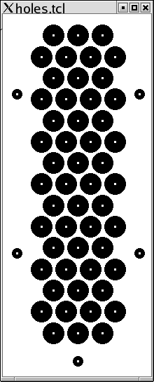
This program is run and it draws the template I need.
Using a screen shot program (gimp) I generated the PNG
file below:
The big holes are air inlet holes and the small holes are mounting holes. Finally, I printed the template out and verified that it was the right size. I actually had to iterate several times to get the right pattern of air inlet holes that are about 1/4" in diameter.
The remaining steps are memorialized in pictures below:

| This is the printed out template getting ready to be cut to size. |

| Next, the cut out template is attached to an 1/8 inch piece of acrylic using tape. |

| Now, I cut the acrylic lengthwise using my band saw. |

| Next, I cut the acrylic crosswise using the band saw. |

| I resecure the two sides that were cut free using tape again. |

| A piece of wood is used as a backing to cut the plastic. |

| I drilled one hole and stuck a 1 inch 4-40 round head screw through the hole and attached with a nut on back. |

| The remaining 4 mouting holes were drilled out and additional 4-40 hardware is used to securely attach the plastic to the wood. |

| This washed out picture shows all the acrylic plastic debris from drilling out 3/4 of the holes. The flash makes everything look well illuminated. In fact, my drill press is in a rather dimly lit portion of my garage and I had difficulty centering the drill bit over the holes. |

| The holes look sort of like the template with one or two holes that overlap. |

| Now I carefully align the plastic so that it will not run into the transformer when it is installed on the inside. For now, the plastic is used as a drilling template for drilling air holes out of the box. |

| The mounting holes are drilled first and the plastic template is attached using 3/8" 4-40 hardware. I should have taken a picture after the plastic was bolted down, but I forget. |

| After all the holes are drilled into the box, the box looks a bit like swiss cheese. Again, one bunch of holes got too close together and I had to trim them a little with diagonal cutters so that sharp metal did not poke out. |

| The filter material is a piece of Scotch-Brite® abrasive material. It is to be sandwiched between the plastic and the box on the inside. The plastic will sit on top of some 1/4" spacers. You can see 4 of the 5 spacers in the picture. |

| Using scissors, the filter material is cut into a rectangle that fits snugly between the 5 spacers. Each spacer is attached using 1/4" #6-32 round head screw and #6 lock washer. The lock washer is inside the box next to the spacer. |

| Next, the plastic is placed on top of the spacers and screwed down using 1/4" #6-32 round head screws and #6 lock washers. Again, the lock washer is next to the spacer. |

| Finally, the lid is placed on to verify that nothing bumps into the transformer. You can see the place where I messed up in the middle of the drilled holes. However, the filter is quite functional since it easily lets air pass through and traps any large metal chips. |