This is the Revision A verion of the Bench RoboBrick. The status of this project is abandoned.
This document is also available in PDF format.
The Bench RoboBrick provides a way of connected a bench power supply to a RoboBrick Hub module to power all of the RoboBricks.
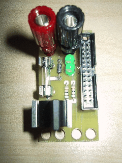
A picture of the Bench-A RoboBrick is shown below:
The hardware consists of a circuit schematic and a printed circuit board.
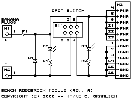
The schematic for the Bench RoboBrick is shown below:
The parts list kept in a separate file -- bench.ptl.
The printed circuit board files are listed below:
After the boards have been manufactured, assembled, and tests, there are usually a number of issues that come and need to be recorded. This section of the document is reserved for thoses issues.