This is the Revision B verion of the Birod4 RoboBrick. The status of this project that it has been replaced by the BIROD5 RoboBrick.
This document is also available as a PDF document.
The BIROD2 RoboBrick is used to connect to up to 2 of the Sharp® GP2D05 IROD (InfraRed Optical Distance) measuring sensors. This version of the Sharp chip provides a single bit of information for when the sensor is within a fixed distance an object.
The basic operation is to send a query to the BIROD2 RoboBrick to read the 2 bits of data. The programmer can download a complement mask to cause any of the bits to be complemented prior to reading.
There is an enable mask that allows the programmer to individually enable and disable one or the other IROD. In addition, there is an alternate bit which, when set, causes the IROD's to be alternately strobed. The alternate bit would be set if you are concerned that one sensor might interfere with another.
The BIROD2 RoboBrick supports RoboBrick Interrupt Protocol. The interrupt pending bit is set whenever the the formula:
L&(~I) | H&I | R&(~P)&I | F&P&(~I)]is non-zero, where:
The BIROD2 RoboBrick supports both the standard shared commands and the shared interrupt commands in addition to the following commands:
Command Send/
ReceiveByte Value Discussion 7 6 5 4 3 2 1 0 Read Inputs Send 0 0 0 0 0 0 0 0 Return input values ab (after XOR'ing with complement mask) Receive 0 0 0 0 0 0 a b Read Raw Send 0 0 0 0 0 0 0 1 Return raw data ab (without XOR'ing with complement mask) Receive 0 0 0 0 0 0 a b Read Alternate Bit Send 0 0 0 0 0 0 1 0 Return alternate bit a Receive 0 0 0 0 0 0 0 a Read Enable
Complement MaskSend 0 0 0 0 0 0 1 1 Return enable mask ee and complement mask cc Receive 0 0 0 0 e e c c Read High
Low MaskSend 0 0 0 0 0 1 0 0 Return high mask hh and low mask ll Receive 0 0 0 0 h h l l Read Raising
Falling MaskSend 0 0 0 0 0 1 0 1 Return raising mask rr and falling mask ff Receive 0 0 0 0 r r f f Set Alternate Bit Send 0 0 0 0 0 1 1 a Set the alternate bit to a. Set Enable
Complement MaskSend 0 0 0 1 e e c c Set enable mask to ee and complement mask to cc. Set High Low Mask Send 0 0 1 0 h h l l Set high mask to hh and low mask to ll. Set Raising Falling Mask Send 0 0 1 1 r r f f Set raising mask to rr and falling mask to ff. Read Interrupt Bits Send 1 1 1 0 1 1 1 1 Return the interrupt pending bit p and the interrupt enable bit e. Receive 0 0 0 0 0 0 e p Set Interrupt Bit Commands Send 1 1 1 1 0 c c c Execute shared set interrupt command ccc. Shared Commands Send 1 1 1 1 1 c c c Execute shared command ccc.
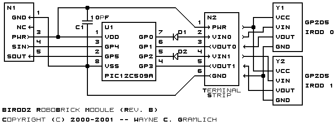
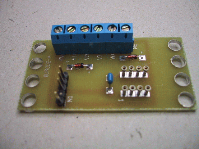
The hardware consists of a circuit schematic and a printed circuit board.
The schematic for the Birod2 RoboBrick is shown below:
The parts list kept in a separate file -- birod2.ptl.
The table below provides the color code for connecting Sharp® GP2D05's to the BIROD2 RoboBrick:
IROD Pin Symbol Wire Color Connect To RoboBrick Pin 1 Vin Green VIN0 or VIN1 2 or 4 2 Ground Black GND 1 3 Vout Blue VOUT0 or VOUT1 3 or 5 4 Vcc Red PWR 6
The available printed circuit boards are listed below:
The BIROD2 software is available as one of:
The BIROD2 test software is available as one of:
The following fabrication issues came up: