This is the Revision A verion of the Line3 module. The status of this project is finished.
This document is also available in PDF format.
The Line3 module has 3 infrared (IR) sensors for sensing lines on flat surfaces. There are sensor that straddle the line and one that can detect when the line simply ends.
{more goes here.}
In addition to the common shared commands and the shared interrupt commands, the Line3 RoboBrix supports following commands:
| Command | Send/ Receive |
Byte Value | Discussion | |||||||
|---|---|---|---|---|---|---|---|---|---|---|
| 7 | 6 | 5 | 4 | 3 | 2 | 1 | 0 | |||
| Read Interrupt Bits | Send | 1 | 1 | 1 | 0 | 1 | 1 | 1 | 1 | Return the interrupt pending bit p and the interrupt enable bit e. |
| Receive | 0 | 0 | 0 | 0 | 0 | 0 | e | p | ||
| Set Interrupt Commands | Send | 1 | 1 | 1 | 1 | 0 | c | c | c | Set Interrupt Command ccc. |
| Shared Commands | Send | 1 | 1 | 1 | 1 | 1 | c | c | c | Execute common shared command ccc |
The hardware consists of a circuit schematic and a printed circuit board.
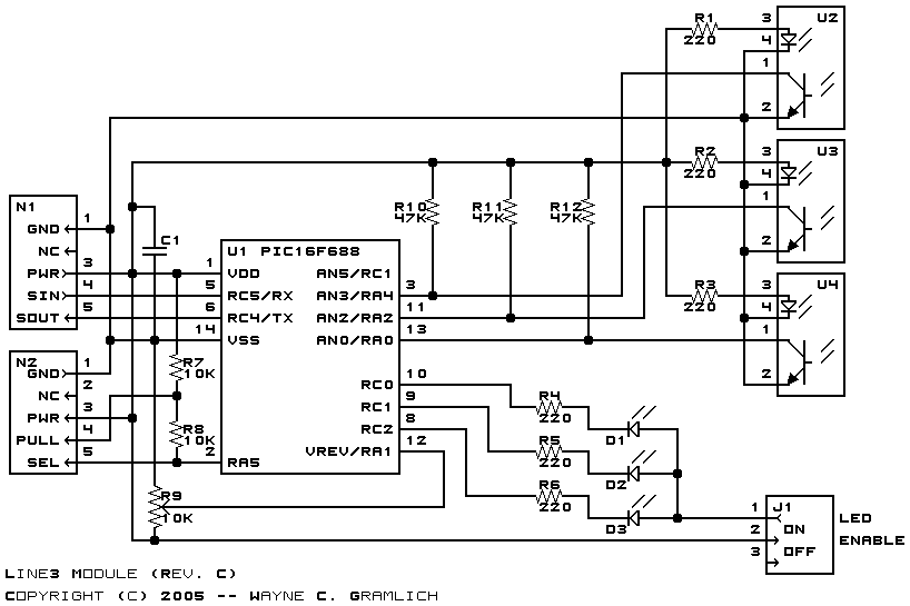
The schematic for the Line3 RoboBrix is shown below:
The parts list kept in a separate file -- line3.ptl.
The printed circuit board files are listed below:
The Line3 software is available as one of:
Any fabrication iusses will be listed here.