This is the Revision A verion of the ProtoPIC8Pin RoboBrick. The status of this project is replaced by the ProtoPic RoboBrick.
This document is also available as a PDF document.
The ProtoPIC8Pin RoboBrick is a RoboBrick with a socket for an 8-pin PIC (either a PIC12C519 or a PIC12C672, or equivalent) and the RJ11 jack. The rest of the board has plated through holes on a .1 inch grid for attachining other components. A jumper selects whether the SIN pin is attached to GP3 or GP4.
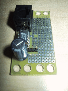
A picture of a ProtoPIC8Pin is shown below:
The hardware consists of a circuit schematic and a printed circuit board.
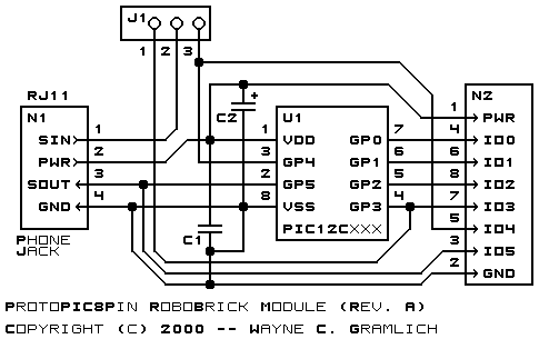
The schematic for the Protopic8pin RoboBrick is shown below:
The parts list kept in a separate file -- protopic8pin.ptl.
The printed circuit files are listed below:
After the boards have been manufactured, assembled, and tests, there are usually a number of issues that come and need to be recorded. This section of the document is reserved for thoses issues.