This is the Revision A version of the InOut10 RoboBrick. The status of this project is that it has been replaceed by the revision C version.
This document is also available in PDF format.
The InOut10 RoboBrick provides the ability to input and output 10 bits of data. The direction of each bit can be changed under program control.
The basic operation is to send a query to the In8 RoboBrick to read the 4 bits of data. The programmer can download a complement mask to cause any of the bits to be complemented prior to reading.
The In8 RoboBrick supports RoboBrick Interrupt Protocol. The interrupt pending bit is set whenever the the formula:
L&(~I) | H&I | R&(~P)&I | F&P&(~I)]is non-zero, where:
The In8 RoboBrick supports both the standard shared commands and the shared interrupt commands in addition to the following commands:
Command Send/
ReceiveByte Value Discussion 7 6 5 4 3 2 1 0 Read Inputs Low Send 0 0 0 0 0 0 0 0 Return low order 5-bits of input iiiii (after XOR'ing with complement mask) Receive 0 0 0 i i i i i Read Inputs High Send 0 0 0 0 0 0 0 1 Return high order 5-bits of input IIIII (after XOR'ing with complement mask) Receive 0 0 0 I I I I I Read Complement Mask Low Send 0 0 0 0 0 0 1 0 Return low order 5-bits of complement mask ccccc Receive 0 0 0 c c c c c Read Complement Mask High Send 0 0 0 0 0 0 1 1 Return high order 5 bits of complement mask CCCCC Receive 0 0 0 C C C C C Read Direction Mask Low Send 0 0 0 0 0 1 0 0 Return low order 5-bits of direction mask ddddd Receive 0 0 0 d d d d d Read Direction Mask High Send 0 0 0 0 0 1 0 1 Return high order 5 bits of direction mask DDDDD Receive 0 0 0 D D D D D Read Raw Low Send 0 0 0 0 0 1 1 0 Return low order 5-bits of raw input data rrrrr (without XOR'ing with complement mask) Receive 0 0 0 r r r r r Read Raw High Send 0 0 0 0 0 1 1 1 Return high order 5-bits of raw input data RRRRR (without XOR'ing with complement mask) Receive 0 0 0 R R R R R Read Low Mask Low Send 0 0 0 0 1 0 0 0 Return low order 5-bits of low mask lllll Receive 0 0 0 l l l l l Read Low Mask High Send 0 0 0 0 1 0 0 1 Return high order 5-bits of low mask LLLLL Receive 0 0 0 L L L L L Read High Mask Low Send 0 0 0 0 1 0 1 0 Return low order 5-bits of the high mask hhhhh Receive 0 0 0 h h h h h Read High Mask High Send 0 0 0 0 1 0 1 1 Return high order 5 bits of the high mask HHHHH Receive 0 0 0 H H H H H Read Raising Mask Low Send 0 0 0 0 1 1 0 0 Return low order 5-bits of the raising mask rrrrr Receive 0 0 0 r r r r r Read Raising Mask High Send 0 0 0 0 1 1 0 1 Return high order 5 bits of the raising mask RRRRR Receive 0 0 0 R R R R R Read Falling Mask Low Send 0 0 0 0 1 1 1 0 Return low order 5-bits of the falling mask fffff Receive 0 0 0 f f f f f Read Falling Mask High Send 0 0 0 0 1 1 1 1 Return high order 5-bits of the falling mask FFFFF Receive 0 0 0 F F F F F Read Outputs Low Send 0 0 0 1 0 0 0 0 Return low order 5-bits of the outputs ooooo Receive 0 0 0 o o o o o Read Outputs High Send 0 0 0 1 0 0 0 1 Return high order 5-bits of the outputs OOOOO Receive 0 0 0 O O O O O Set Complement Mask Low Send 0 0 0 1 0 0 1 0 Set low order 5-bits of complement mask to ccccc Send 0 0 0 c c c c c Set Complement Mask High Send 0 0 0 1 0 0 1 1 Set high order 5 bits of complement mask to CCCCC Send 0 0 0 C C C C C Set Direction Mask Low Send 0 0 0 1 0 1 0 0 Set low order 5-bits of direction mask to ddddd Send 0 0 0 d d d d d Set Direction Mask High Send 0 0 0 1 0 1 0 1 Set high order 5 bits of direction mask of DDDDD Send 0 0 0 D D D D D Reset Outputs Send 0 0 0 1 0 1 1 0 Set all 10 bits of outputs to 0 Reset Everything Send 0 0 0 1 0 1 1 1 Reset all registers to 0 and set direction bits to 1 (input) Set Low Mask Low Send 0 0 0 1 1 0 0 0 Set low order 5-bits of low mask to lllll Send 0 0 0 l l l l l Set Low Mask High Send 0 0 0 1 1 0 0 1 Set high order 5-bits of low mask to LLLLL Send 0 0 0 L L L L L Set High Mask Low Send 0 0 0 1 1 0 1 0 Set low order 5-bits of the high mask to hhhhh Send 0 0 0 h h h h h Set High Mask High Send 0 0 0 1 1 0 1 1 Set high order 5 bits of the high mask to HHHHH Send 0 0 0 H H H H H Set Raising Mask Low Send 0 0 0 1 1 1 0 0 Set low order 5-bits of the raising mask to rrrrr Send 0 0 0 r r r r r Set Raising Mask High Send 0 0 0 1 1 1 0 1 Set high order 5 bits of the raising mask to RRRRR Send 0 0 0 R R R R R Set Falling Mask Low Send 0 0 0 1 1 1 1 0 Set low order 5-bits of the falling mask to fffff Send 0 0 0 f f f f f Set Falling Mask High Send 0 0 0 1 1 1 1 1 Set high order 5-bits of the falling mask to FFFFF Send 0 0 0 F F F F F Set Outputs Low Send 0 0 1 o o o o o Set low order 5-bits to ooooo Set Outputs High Send 0 1 0 O O O O O Set high order 5-bits to OOOOO Set Output Bit Send 0 1 1 v b b b b Set output bit bbbb to v Read Interrupt Bits Send 1 1 1 0 1 1 1 1 Return the interrupt pending bit p and the interrupt enable bit e. Receive 0 0 0 0 0 0 e p Set Interrupt Commands Send 1 1 1 1 0 c c c Set Interrupt Command ccc. Shared Commands Send 1 1 1 1 1 c c c Execute Shared Command ccc.
The hardware consists of a circuit schematic and a printed circuit board.
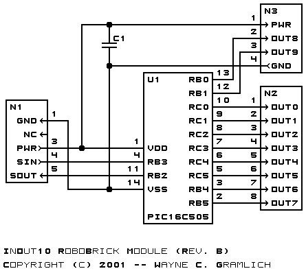
The schematic for the InOut10 RoboBrick is shown below:
The parts list kept in a separate file -- inout10.ptl.
The printed circuit files are listed below:
The InOut10 software is available as one of:
The InOut10 test suite is available as one of:
The following fabrication issues came up: